Home

Uitbreiding het einde haak buck converter feedback loop design Vorming Teken verzending

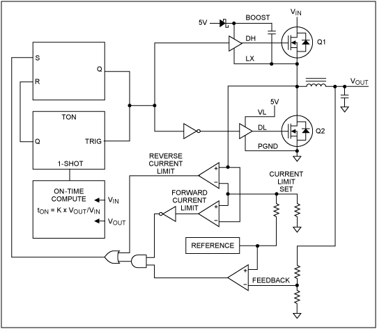
DC to DC Buck Converter Tutorial & Diagram | Maxim Integrated

Designing Compensator Networks | DigiKey

Ridley Engineering | - [020] Buck-Boost Converter with Current-Mode Control

Modeling and Control for a Current-Mode Buck Converter with a Secondary LC  Filter | Analog Devices
Modeling and Control for a Current-Mode Buck Converter with a Secondary LC Filter | Analog Devices

Closed loop buck converter | Download Scientific Diagram

Closed-Loop Buck Converter Modeling & Simulation - File Exchange - MATLAB  Central
Closed-Loop Buck Converter Modeling & Simulation - File Exchange - MATLAB Central

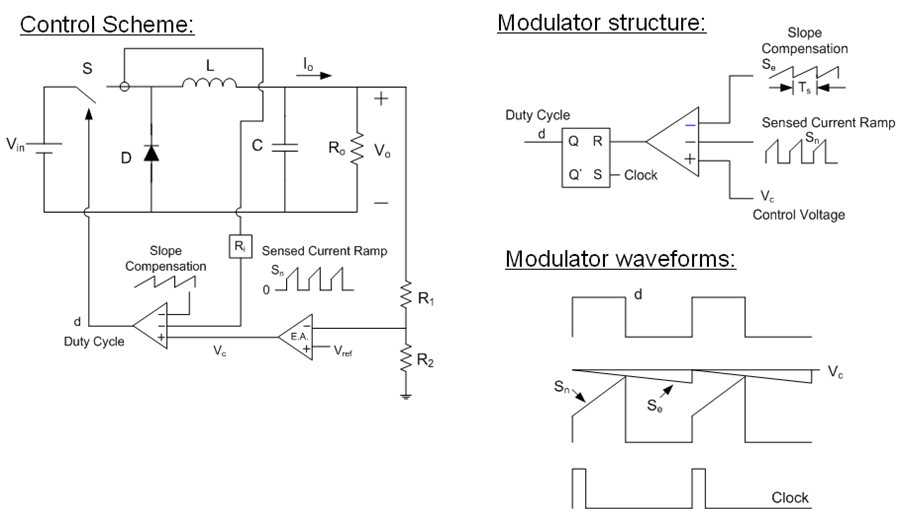
Compensation Design for Peak Current-Mode Buck Converters | Richtek  Technology
Compensation Design for Peak Current-Mode Buck Converters | Richtek Technology

Power Supply Design Notes: Simulating a buck converter - Power Electronics  News
Power Supply Design Notes: Simulating a buck converter - Power Electronics News

Modeling and Loop Compensation Design of Switching Mode Power Supplies,  Part 1 - EDN
Modeling and Loop Compensation Design of Switching Mode Power Supplies, Part 1 - EDN

DC to DC Buck Converter Tutorial & Diagram | Maxim Integrated

Figure 1 from Feedback Loop Analysis and Optimized Compensation Slope of  the Current-Mode Buck DC-DC Converter in DCM | Semantic Scholar
Figure 1 from Feedback Loop Analysis and Optimized Compensation Slope of the Current-Mode Buck DC-DC Converter in DCM | Semantic Scholar

Feedback control of a buck converter: v in and vo are the input and... |  Download Scientific Diagram
Feedback control of a buck converter: v in and vo are the input and... | Download Scientific Diagram

Stability Analysis of Feedback Loops Part Two

The Conventional Feedback Buck Converter. | Download Scientific Diagram

Peak Current Mode and Continuous Current Mode DC-to-DC Converter Modeling  and Loop Compensation Design Considerations | Analog Devices
Peak Current Mode and Continuous Current Mode DC-to-DC Converter Modeling and Loop Compensation Design Considerations | Analog Devices

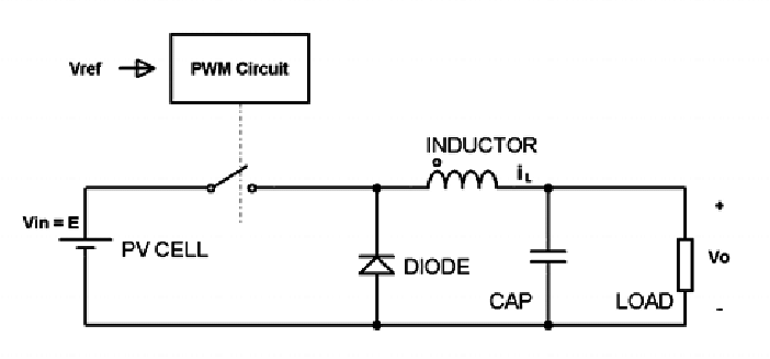
Design and Simulation of DC-DC Buck Converter using Cadence Tool | Semantic  Scholar
Design and Simulation of DC-DC Buck Converter using Cadence Tool | Semantic Scholar

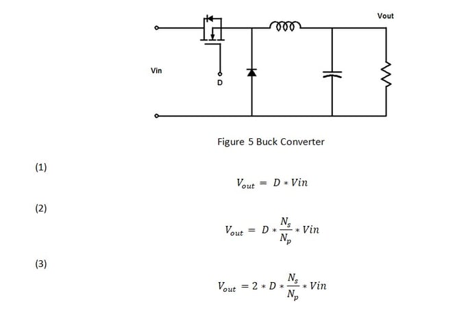
PWM Step-Down Converter Design (Buck Converters) | by Felix Blanco Jr. |  Medium
PWM Step-Down Converter Design (Buck Converters) | by Felix Blanco Jr. | Medium

P-MOSFET Buck Converter (Switching Power Supply) closed loop 01 - CircuitLab

Error amplifier limitations in high-performance regulator applications - EDN

Table 4 from Practical Feedback Loop Design Considerations for Switched  Mode Power Supplies | Semantic Scholar
Table 4 from Practical Feedback Loop Design Considerations for Switched Mode Power Supplies | Semantic Scholar

Peak Current Mode and Continuous Current Mode DC-to-DC Converter Modeling  and Loop Compensation Design Considerations | Analog Devices
Peak Current Mode and Continuous Current Mode DC-to-DC Converter Modeling and Loop Compensation Design Considerations | Analog Devices
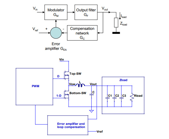
Control Methods (Voltage Mode, Current Mode, Hysteresis Control)

Overview and Comparison of Power Converter Stability Metrics | 2018-05-01 |  Signal Integrity Journal
Overview and Comparison of Power Converter Stability Metrics | 2018-05-01 | Signal Integrity Journal